SMT 요구 사항에 맞는 올바른 스텐실을 선택하는 방법

SMT 요구 사항에 맞는 올바른 스텐실을 선택하는 방법

표면 실장 기술 프로젝트를 위한 스텐실을 제작할 계획이라면 필요한 스텐실을 결정하는 데 도움이 되는 몇 가지 요소를 잘 알고 있어야 합니다. 이러한 요소는 가격, 모양 및 치수입니다. 이러한 요소를 고려하면 최선의 선택을 하는 데 도움이 됩니다.

치수

스텐실은 보드 데이터를 수용할 수 있는 정확한 치수를 가져야 합니다. 이를 유효 영역이라고 합니다. 유효 영역은 스텐실의 중앙 부분으로 SMT 기판의 패드에 맞게 절단할 수 있습니다. 스텐실 주변의 나머지 공간을 스텐실 마진이라고 합니다. 스텐실은 이 영역을 넘어 절단할 수 없습니다.

SMT 스텐실 기술에는 크게 5가지 유형이 있습니다. 여기에는 레이저 컷, 전기 성형, 화학 에칭 및 하이브리드가 포함됩니다. 화학 에칭 금속 스텐실은 스텝 스텐실에 매우 유용합니다. 이 스텐실은 양면을 화학적으로 밀링하여 중앙에 약간의 모래시계 모양이 있는 거의 직선형 벽을 만듭니다.

텍스처

스텐실과 관련해서는 다양한 옵션을 사용할 수 있습니다. 스텐실을 구매하거나 직접 DIY할 수 있습니다. 스텐실은 플로터를 사용하여 잘라낸 디자인입니다. 스텐실의 품질과 크기는 플로터의 설정에 따라 달라집니다. 스텐실을 자르기 전에 힘과 속도 설정이 올바른지 확인하세요. 힘은 끈적끈적한 뒷면을 손상시키지 않고 비닐을 자를 수 있을 만큼 충분히 강해야 합니다. 속도는 가능한 한 빨리 스텐실을 꺼낼 수 있을 만큼 충분히 빨라야 합니다. 그러나 너무 빨리 자르면 직사각형의 모서리가 찢어질 수 있습니다.

표면 실장 기술에 사용되는 스텐실은 일반적으로 스테인리스 스틸 호일로 만들어집니다. 레이저를 사용하여 표면 실장 장치에 맞게 절단합니다. 이 스텐실은 기판에 배치되어 솔더 페이스트를 도포하는 데 사용됩니다. 스텐실을 사용하면 수작업 없이도 솔더 페이스트를 정확하게 배치할 수 있습니다. 또한 스텐실을 사용하면 시간과 노력을 절약할 수 있습니다.

가격

스텐실을 구매할 때 고객은 자신의 요구 사항에 적합한 스텐실을 찾기 위해 주의를 기울여야 합니다. 고려해야 할 두 가지 주요 요소는 스텐실 두께와 보드 데이터입니다. 스텐실 두께는 보드에서 페이스트를 떼어내는 데 도움이 됩니다. 또한 스텐실 크기는 스텐실의 중앙 부분인 유효 영역(EA) 내에 있어야 합니다. 스텐실의 나머지 부분을 마진이라고 하며 잘라낼 수 없습니다.

스텐실의 크기는 모든 자동 솔더 페이스트 프린터의 중요한 파라미터입니다. PCB마다 내부 크기가 다르기 때문에 스텐실은 프린터의 프레임 크기에 맞아야 합니다.

가용성

스텐실은 다양한 데코레이션 프로젝트를 위한 훌륭한 옵션입니다. 방에 페인트를 칠하거나 가구에 독특한 디자인을 추가할 때 스텐실을 사용하면 깔끔하고 선명한 이미지를 얻을 수 있습니다. 페인트 브러시와 달리 스텐실은 재사용이 가능하며 수년간 사용할 수 있습니다.

BGA 칩을 위한 독점 레이아웃 팁

BGA 칩을 위한 독점 레이아웃 팁

To layout a BGA chip, you should understand its footprint. There are several different types of layouts. You can choose from Vias, Fanouts, and Fiducial marks. The datasheet for the NCP161 chip provides the recommended pad size and shape.

Fanouts

If you’re designing a PCB with BGA chips, it is important to consider the best routing pattern for your part. A high pin-count BGA chip, for example, requires meticulous planning to achieve the right escape routing patterns. You’ll need to take into account factors such as the component’s pitch and the desired spacing between its balls.

The best route for a BGA chip consists of two basic steps. First, you should calculate the number of layers needed to route the signal pins. There are two basic routes you can use for your BGA: a traditional fanout, or a dog-bone fanout. Typically, the dog-bone fanout method is used for larger-pitch BGAs. It allows you to route the outer two rows of pins on the surface layer, while leaving the remaining inner pads free of vias.

Fiducial marks

BGA chips are widely used in electronic assembly. However, because of their peculiar shape, they present a higher risk of short circuits during soldering. The right layout tips and practices can help you avoid these problems. In this article, you will learn how to correctly place BGA chips on your PCB in order to maximize the soldering effect.

The first step in proper BGA chip layout is to ensure the proper spacing of the components. Usually, the pads are not numbered sequentially but rather in a column-row format. The columns are numbered from left to right, starting with A1. Pin A1 is typically indicated by a mark on the top side of the chip.

Corner marks

When it comes to PCB layout, the same rules apply whether you’re working with BGA chips or other types of electronic components. The best way to achieve optimum performance is to make sure that your BGAs are mounted with a powerful X-ray system. You should also use a vision placement system to ensure that your BGAs are positioned correctly.

When working with high-pin-count BGA chips, planning is key. You may need to add several board layers to accommodate all the escape routing. You must also carefully consider the placement of components before you begin routing the traces.

Power integrity

High-pin-count BGA chips require careful planning before routing traces. You should also take into account the routing channels required for vias that exit the pins. In some cases, it may be necessary to add two additional board layers to accommodate the extra pins. Moreover, BGAs have multiple rows and columns, which requires careful placement of components.

The first step is to decide where to place the BGAs. Some designers use flip-chip BGAs, in which some pins are removed from the interior rows. Others use microvias, which are drilled by laser. Blind vias are also an option, but they are more expensive. Blind vias are usually included in the most expensive layout plans.

Hasl 무연과 Hasl 무연의 차이점은 무엇인가요?

What’s the Difference Between Hasl Lead Free and Hasl Lead Free?

HASL is a tin-lead alloy. It forms joints easily and is often used in hand-soldering. Its strong joints are made possible by the close molecular bonding of the two metals. This makes it a preferred finish for high-reliability applications.

HASL is a tin-lead alloy

HASL is a tin and lead alloy that is often used for electronic circuit boards. It forms strong joints easily and is commonly used for hand soldering. The two types of HASL are similar and will interact on a molecular level. These similarities make HASL an excellent choice for high-reliability applications.

Tin-lead solder has several unique characteristics. The chemical and physical properties of tin-lead solder have been the subject of extensive research over the past 50 years.

It is thinner

There are several advantages of lead free PCBs compared to HASL. Among these advantages, HASL has the best shelf life. In addition, lead free PCBs are more spreadable. This makes them better for soldering copper. However, there are several disadvantages of lead-free PCBs.

Lead-free HASL is thinner and has better coplanarity than lead-lead HASL. The difference in solder coating thickness is approximately half the lead-lead finish. Lead-free HASL has a higher melting point and requires a slight adjustment in the soldering process. The process is similar to standard HASL but uses a special flux. This flux helps in activating the copper surface of PCB. When solder is applied to the board, it is important that it has a uniform thickness. The air knife is an important tool in this process.

It is more uniform

Since the lead-free movement began in the electronics industry in 2006, lead-free soldering has become a popular method for assembling printed circuit boards. Before the move towards lead-free manufacturing, this method was considered to be an outdated technology. It was, however, the predominant finish method in North America, Europe, and Asia outside of Japan. This method is now considered to be the preferred method for lead-free production. Several Chinese printed circuit board manufacturing plants have installed lead-free HASL lines to meet the growing demand in Europe. Lead-free HASL is also gaining popularity in India and South East Asia.

The lead-free alloy is much less toxic to humans than the HASL version. Its eutectic temperature is about two hundred and seventy degrees, which is significantly lower than the HASL lead-free alloy. Moreover, it has a higher degree of mechanical strength and brightness than its lead-tin counterpart. However, there are some disadvantages associated with lead-free, such as its higher cost.

It has a longer shelf life

Hasl lead-free has a longer shelf-life than lead-lead solder. It is also cheaper and can be reworked. However, it does not provide a smooth finish and is unreliable in fine pitch applications. It also creates solder bridging along the board, resulting in a less uniform mount pad surface. Immersion tin solder is another option. It is a white metallic substance that is applied directly to copper. The two metals are very attracted to each other.

Lead-free solder has a longer shelf life than tin lead, but it has a few disadvantages. Tin lead is toxic and can cause the environment to suffer. Lead-free solder is more environmentally friendly. It is also easier to clean. Unlike lead-based solder, Hasl lead free is compatible with most alternative finishes.

It is RoHS compliant

The lead-free version of HASL is similar to conventional HASL PCB but does not use tin-lead in the production process. It is a RoHS-compliant alternative, but may not be suitable for ultra-tiny parts, such as tiny LEDs.

Lead-free HASL has a higher temperature range of 260 to 270°C, a temperature regime that can cause skewed results and board failure. HASL lead free is also less effective for SMD/BGA components with element pitches below 20 mm. In addition, LF HASL is less uniform than HASL Pb/Sn. It can also cause shorting due to lead-free vapors exuded during the application process.

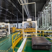
PCB 조립 비용에 영향을 미치는 요인

PCB 조립 비용에 영향을 미치는 요인

PCB 조립 서비스 시장에 있다면 가격에 영향을 미치는 몇 가지 요소가 있습니다. 여기에는 맞춤형 사양, 레이어 수, 리드 타임, 노동의 질 등이 포함됩니다. 이러한 요소를 이해하면 PCBA 조립 서비스와 협상하는 데 도움이 됩니다. PCB 조립의 전체 비용을 절감하려면 다음 팁을 염두에 두십시오.

레이어 수

PCB 조립 비용에는 레이어 수를 비롯한 여러 가지 요인이 영향을 미칩니다. 레이어 수가 많을수록 필요한 생산 단계와 필요한 원자재 수가 증가합니다. 레이어 수가 많을수록 라미네이션 공정이 더 복잡해지기 때문에 비용도 증가합니다. 예를 들어, 4레이어 PCB는 패널이 2개인 PCB보다 비용이 더 많이 듭니다.

레이어 수를 선택할 때는 수를 결정하기 전에 보드의 목적을 이해하는 것이 중요합니다. 레이어 수는 사용되는 기계의 유형과 전자 회로의 복잡성에 따라 결정됩니다. 일반적으로 하이테크 애플리케이션에는 많은 레이어가 필요합니다.

리드 타임

리드 타임은 PCB 조립 비용을 비교할 때 고려해야 할 가장 중요한 요소 중 하나입니다. 리드 타임에 따라 생산 공정에 소요되는 시간과 PCB 어셈블리 비용이 결정됩니다. 리드 타임은 회사마다 크게 다를 수 있으므로 적시에 요구 사항을 충족할 수 있는 공급업체를 찾는 것이 중요합니다.

리드 타임은 고객 리드 타임, 제조 리드 타임, 배송 리드 타임의 세 가지 범주로 나뉩니다. 예를 들어, 특정 재료를 주문하는 경우 재료가 배송되기까지 몇 주를 기다려야 할 수 있습니다. 마찬가지로 공급업체에서 원자재를 주문하는 경우 다른 공급업체에서 주문할 때보다 리드 타임이 더 길어집니다. 리드 타임을 줄이려면 공급업체가 재고를 보유하고 있는지, 필요한 경우 신속하게 재료를 배송할 수 있는지 확인해야 합니다.

노동의 질

PCB 조립 비용이 저렴해 보일 수 있지만, 외국에서 조립할 경우 비용이 크게 올라갈 수 있습니다. 예를 들어, 남아시아에서 조립된 PCB는 북미나 서유럽에서 조립된 것보다 몇 배나 더 비쌉니다. 또한 해외에서 PCB를 조립하면 취급, 배송 및 통신 지연으로 인해 비용이 증가합니다. 따라서 저렴한 PCB 조립 비용이 매력적일지라도 인건비와 패키징의 품질을 고려하는 것이 중요합니다.

PCB 조립 비용도 수량에 영향을 받을 수 있습니다. 수량이 많을수록 규모의 경제로 인해 PCB 조립 비용이 낮아집니다. 고품질 PCB 조립 서비스는 일반적으로 소량 주문을 제공하는 서비스보다 더 많은 비용을 청구합니다. 그러나 PCB 어셈블리가 소량 생산으로 제한되는 경우 더 저렴한 국가를 선택하여 PCB를 제조할 수 있습니다.

보드 설계의 복잡성

보드 설계의 복잡성은 PCB 조립 비용에 큰 영향을 미칩니다. 보드 설계가 복잡할수록 제조에 더 많은 시간과 노력이 소요됩니다. 예를 들어, PCB 설계에 BGA를 추가한다는 것은 완전히 새로운 검사와 추가 조립 단계를 의미합니다. 또한 PCB 제조업체의 비용은 준수해야 하는 표준의 영향을 받습니다. 예를 들어, 계약 제조업체는 항공우주 산업을 위한 IPC 클래스 III PCB를 제작하기 위해 필요한 인증에 투자해야 합니다.

PCB 조립 비용은 보드 설계의 복잡성, 생산되는 제품의 유형 및 조립 방법과 관련된 요소의 영향을 받습니다. 이러한 요인에 관계없이 PCB 조립 비용을 최소화하기 위해 취할 수 있는 몇 가지 단계가 있습니다. 첫째, 설계 프로세스가 핵심입니다. 제조 공정, 보드 크기, 부품 크기의 불일치는 모두 PCB 조립 비용에 영향을 미칩니다.

PCB 제조업체 또는 PCB 조립업체 평가를 위한 팁

PCB 제조업체 또는 PCB 조립업체 평가를 위한 팁

PCB 제조업체 또는 어셈블러를 선택할 때는 해당 업체가 프로젝트를 처리할 수 있는 역량을 갖추고 있는지 확인해야 합니다. 즉, 처리 능력과 도구가 최신의 최첨단이어야 합니다. 즉, 최신 기술로 수작업과 자동화 작업을 모두 처리할 수 있어야 합니다.

PCB 제조업체와 조립업체 선택하기

PCB 어셈블러와 제조업체를 결정할 때는 각 업체가 귀사에 제공할 수 있는 이점을 고려해야 합니다. PCB 어셈블러는 제조 관련 문제나 조달 문제를 알려줌으로써 귀사가 한발 앞서 나갈 수 있도록 도와줄 수 있습니다. PCB 제조업체는 규정 준수 문제를 지원하고 문서화를 보장할 수 있습니다. 비용이 많이 드는 실수를 방지하고 가능한 최고 품질의 제품을 보장할 수 있습니다.

PCB 어셈블러를 이용하면 자체 재고를 보유할 필요가 없으므로 시간과 비용을 절약할 수 있습니다. 숙련된 PCB 제조업체는 다른 부품의 비용 절감에도 도움을 줄 수 있습니다. 적은 비용으로 더 높은 품질을 얻을 수 있으므로 평판이 좋은 제조업체를 찾는 것이 좋습니다. 그러나 PCB 어셈블러의 비용은 귀하의 위치로부터의 거리, 주문의 크기 및 필요한 배송 옵션에 따라 달라질 수 있다는 점에 유의하는 것이 중요합니다. PCB 어셈블러를 찾을 때는 견적을 제공하고 가격 범위 내에 있는 업체를 찾으십시오.

마지막으로, PCB 어셈블리 회사의 규모를 고려하십시오. 부품은 PCB 예산의 상당 부분을 차지하므로 주문 목록이 많고 업계에서 경험이 풍부한 제조업체와 협력하는 것이 좋습니다. 규모가 클수록 일반적으로 공급업체와 더 나은 가격을 협상할 수 있고 더 많은 주문을 처리할 수 있는 능력이 있습니다.

PCB 제조업체 및 PCB 조립업체와의 연락 유지

PCB 제조업체와 연락을 유지하는 것은 제품이 올바르게 조립되었는지 확인할 수 있는 좋은 방법입니다. 과거에는 PCB 조립이 수작업으로 이루어졌지만, 이제는 자동화 장비로 대체되었습니다. 기계는 사람에 비해 더 정확하고 조립 프로세스의 속도를 높일 수 있습니다. 또한 더 빠르게 작업할 수 있고 공정 중에 피로를 느끼지 않습니다.

PCB 조립은 여러 가지 요소를 신중하게 고려해야 하는 기술 프로세스입니다. 작은 변화도 비용과 최종 제품 품질에 큰 영향을 미칠 수 있습니다. 일반적으로 PCBA 제조와 조립은 별도의 회사에서 수행하지만 두 가지를 결합할 수도 있습니다. PCB 어셈블러를 선택할 때는 인증 및 모범 사례에 대해 문의하는 것이 중요합니다. IPC 인증을 확인합니다. PCB 어셈블러가 이 인증을 받았다면 최고 수준의 품질 및 정확성 표준을 따르고 있다는 것을 확신할 수 있습니다.

PCB 제조업체와 PCB 조립업체 식별하기

PCB 제조업체와 PCB 조립업체를 구분해야 합니다. PCB는 보드가 작동하는 데 필요한 구성 요소가 포함된 인쇄 회로 기판입니다. 숙련된 PCB 제조업체 및 어셈블러는 PCB 제작에 대한 경험과 전문성을 갖추고 있습니다. 완성된 제품에는 무결점과 높은 정밀도가 요구됩니다.

PCB 어셈블러와 제조업체는 서로 다른 서비스를 제공하며, 이는 가격에 영향을 미칩니다. 가격을 비교하여 회사가 비용 대비 최고의 가치를 제공할 수 있는지 확인해야 합니다. PCB 어셈블리의 가격은 다양할 수 있지만, 생산되는 제품의 품질과 동등해야 합니다. 가격은 또한 주문 규모에 따라 달라집니다. 예를 들어, 표면 실장 어셈블리는 스루홀 어셈블리보다 더 비쌉니다. 회사가 부품 생산 또는 설계 지원을 제공하는지 여부는 PCB 어셈블리 가격에 영향을 줄 수 있는 또 다른 요소입니다.