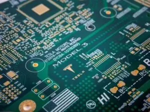
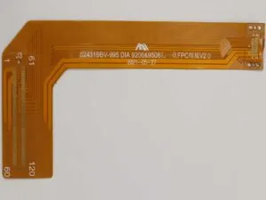
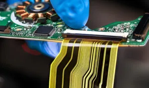
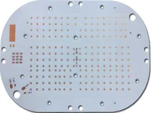
A High Frequency PCB (HF PCB) is a specialized printed circuit board engineered to reliably carry and process signals with frequencies typically starting around 50 MHz to 100 MHz and above, where the behavior of signals transitions from simple electrical currents to electromagnetic waves. The defining characteristic is that the wavelength of the signals becomes comparable to or smaller than the physical dimensions of the board traces and structures, introducing complex high-frequency effects that standard PCBs aren’t designed to handle.
RF PCBs (Radio Frequency Printed Circuit Boards) and Microwave PCBs are specialized circuit boards designed for high-frequency signals, but they differ primarily in their operating frequency ranges, materials, and design complexity:
RF PCBs:
Frequency Range: Typically operate from ~100 MHz up to several GHz (often considered up to ~3 GHz, though definitions vary).
Applications: Wireless communication (WiFi, Bluetooth, cellular base stations/phones), radio transceivers, remote controls, RFID systems, GPS receivers, automotive radar (some), general high-frequency analog circuits.
Key Characteristics:
Materials: Often use specialized FR-4 variants with improved high-frequency properties (lower Dk, lower loss tangent) or entry-level high-frequency laminates (e.g., Rogers RO4000 series, Taconic RF-35, Isola FR408HR). Cost is often a significant factor.
Design Focus: Critical impedance control (e.g., 50 ohms), minimizing signal reflections, managing crosstalk, proper grounding (ground planes), and minimizing parasitic capacitance/inductance. Transmission line structures like microstrip are common.
Complexity: Design is more critical than standard digital PCBs but often less extreme than pure Microwave PCBs. Tolerances are tighter.

Microwave PCBs:
Frequency Range: Operate in the Microwave spectrum, generally starting above ~1 GHz and extending into Millimeter-Wave (mmWave) frequencies (30 GHz, 60 GHz, 77 GHz, and beyond – often up to 100+ GHz).
Applications: Radar systems (automotive, aerospace, defense), satellite communication, point-to-point microwave links (5G backhaul), advanced wireless networks (5G/6G mmWave), sophisticated test equipment, high-speed data links.
RF PCB Key Characteristics:
Materials: Require ultra-low-loss, high-frequency specific laminates with extremely stable dielectric constants (Dk) and very low dissipation factors (Df/Loss Tangent). Common materials include PTFE-based laminates (e.g., Rogers RO3000, RT/duroid 6000 series, TMM series, Taconic TLY/TLX) and specialized ceramics. FR-4 is almost never suitable.
Design Focus: Extreme precision in impedance control (tighter tolerances), minimizing signal loss (insertion loss) is paramount, managing dispersion (signal speed variation with frequency), minimizing skin effect losses, highly controlled phase matching in circuits like phased arrays, complex coupling structures (e.g., edge-coupled filters, Lange couplers), and often 3D electromagnetic field effects. Structures like stripline, grounded coplanar waveguide (GCPW), and intricate planar filters are common.
Common Applications:
Wireless Communication Systems (4G/5G/6G base stations, smartphones, WiFi routers)
Radar Systems (Automotive, Aerospace, Defense)
Satellite Communication
High-Speed Digital Design (Server backplanes, high-speed SerDes links > 10 Gbps)
Test & Measurement Equipment (Network analyzers, oscilloscopes)
Medical Imaging Systems (MRI)
Microwave Radio Links
In Essence:
A High Frequency PCB is defined by its need to manage the complex electromagnetic phenomena that dominate signal behavior at frequencies where traditional “lumped element” circuit theory breaks down. It requires:
Specialized Materials to minimize loss,
Sophisticated Design & Simulation to control impedance, reflections, coupling, and radiation,
Precision Manufacturing to achieve the required physical tolerances.
RF PCBs and Microwave PCBs are specific subsets of High Frequency PCBs, operating within defined portions of the overall HF spectrum.
How to Find a Reliable High Frequency PCB Board Manufacturer in China?
In order to find a reliable high frequency PCB board manufacturer in China, here are some of the things that you need to keep in mind.
• Review the import and export license of the company for smooth exports.
• Look into the company reputation.
• Ask the company for references and counter-check those references.
• Inspect the quality control system certificate for ensuring validity.
Choose the Best High Frequency PCB Board Manufacturer in China
Now that you have an idea about high frequency PCB boards, what you need to do is reach out to the best manufacturer in China. This is where PCBA123 comes into place. It provides outstanding high frequency PCB boards that will blow you away. You can get in touch with the company for customized options.